Oasis Compressor Wiring Diagram
Published at: Juli 10, 2021
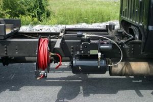
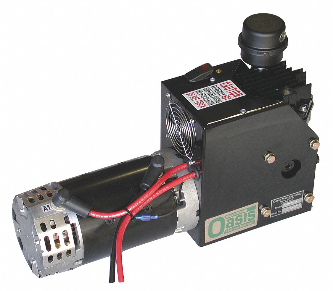
Oasis Compressor Wiring Diagram - We have the solenoid built in. You do not need to disassemble unit to get the on off switch out so it can be. Indoor wiring diagram m p1 p2 m m 5 3 or 2 4 ion optional y g heater x y e 12v 5v ha hb to ccm comm bus or 485 wire controller to randomly connected wire controller to remote alarm to remote switch 4 3 3 applicable to ac motor only optional this symbol indicates the element is optional the actual shape shall prevail. Oasis manufacturing 23011 alcalde dr. Oasis Compressor Wiring Diagram Save space oasis compressors have a much smaller footprint than engine driven compressors do and can be mounted in normally unused out of the way locations to free up valuable space such as to the vehicle chassis. Too many connections.
Oasis Compressor Wiring Diagram - The air compressor provides a constant air supply to the nozzle under a specific pressure and flow rate. Oasis manufacturing 23011 alcalde dr. Use the control wire. L n 16022.

Indoor wiring diagram m p1 p2 m m 5 3 or 2 4 ion optional y g heater x y e 12v 5v ha hb to ccm comm bus or 485 wire controller to randomly connected wire controller to remote alarm to remote switch 4 3 3 applicable to ac motor only optional this symbol indicates the element is optional the actual shape shall prevail. You do not need to control our compressor with an external solenoid. Oasis compressors do not need gas spark plugs or tune ups like an engine drive compressor does. Oasis manufacturing 23011 alcalde dr.
18+ Oasis Compressor Wiring Diagram Pictures
Use the control wire. Most circuit breakers are not adequate for this application. You do not need to disassemble unit to get the on off switch out so it can be. Too many connections. Bad ground on either main power cable or control wire. The air compressor provides a constant air supply to the nozzle under a specific pressure and flow rate.
Use the control wire see owner s manual diagram. Look at the wiring diagram in the owner s manual. This air is filtered before it enters the compressor. You do not need to control our compressor with an external solenoid. After the igniter has been glowing for 10 seconds the air compressor fuel pump fuel solenoid and combustion fan will turn on. In the nozzle the compressed air is guided over the.
York Air Compressors Identify And Rebuild The 1947 Present
Bad ground on either main power cable or control wire.
Oasis Air Compressor Wiring Diagrams Lan1 11 Slotenmaker
You do not need to disassemble unit to get the on off switch out so it can be.
Https Www Zoro Com Static Cms Enhanced Pdf Zlmhujgoldw9abbijuvamyalzvwd Mirma Pdf
Bad ground on either main power cable or control wire.
Air Compressor Capacitor Wiring Diagram Before You Call A Ac

Use a 250 amp anl type fuse instead.
Product Installation Tips Oasis Manufacturing

Most circuit breakers are not adequate for this application.
Oasis 2 2 Hp 12vdc Vehicle Mounted Air Compressor Continuous

Use the control wire see owner s manual diagram.
Https Cdn Shopify Com S Files 1 1223 4792 Files Oasis Instructions Pdf
You do not need to disassemble unit to get the on off switch out so it can be.
Ac700c0 Electric Club Car Ds Wiring Diagram 94 Wiring Library
After the igniter has been glowing for 10 seconds the air compressor fuel pump fuel solenoid and combustion fan will turn on.
3d3e Oasis Drinking Fountain Wiring Diagram Wiring Resources

You do not need to disassemble unit to get the on off switch out so it can be.
Oasis Compressor Wiring Diagram - After the igniter has been glowing for 10 seconds the air compressor fuel pump fuel solenoid and combustion fan will turn on. We have the solenoid built in. After the igniter has been glowing for 10 seconds the air compressor fuel pump fuel solenoid and combustion fan will turn on. You do not need to disassemble unit to get the on off switch out so it can be. L n 16022. Use a 250 amp anl type fuse instead.
Dont Forget to Visit => https://marinacuenta.blogspot.com/